


Next: Center of Mass
Up: Talairach
Previous: Talairach

Figure 40: Talairach Load/Save menus
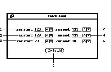
Figure 41: Talairach Fetch Anat popup window.
The following is the procedure to configure the Talairach Coordinate
feature.
-
The first step is to input three cardinal
orientation image volumes
 of the subject brain using the Load
button (39-9).
This is accomplished by pulling down the load menu
as shown in Figure 40 and
sequentially selecting each orientation menu
item (i.e. Sag, Ax & Cor).
As each orientation menu item is selected
the file browser popup window will be displayed (See Section 5).
When loaded, the image filename appears under the respective
display window (39-2).
An alternative to loading three different files is
to extract the three cardinal views from the currently loaded
Anat image volume. This is accomplished by pressing the
Fetch Anat ... button (39-17) and
specifing the desired planes on the Fetch Anat popup window
(Figure 41). The default cardinal planes are
 5 from the volume center (41-1:6).
Then by pressing the Go Fetch! button (41-7),
those planes specified are extracted and loaded into the three orthogonal
view image displays (39-1,15,16).
-
The contrast and brightness of the images can be adjusted using the
Mod Lut button (39-6) to display the
Modify Lut graphical tool as shown in Figure 16.
After adjusting the LUT mapping, pressing
the LUT Range button (39-7) will recalculate
the LUT indices as discussed in Section 8.
-
The orientations can be checked by selecting the
Axis option (39-13) as shown in
Figure 42 and described in
Table 5. A summary of the orientation
conventions is provided below each image (39-5).
Also shown in Figure 42
is the effect of the Plns option (39-13).
The relationship between the image planes is displayed
as a vertical and horizontal lines as described in
Table 10. When any of the planar indices
(39-3) are changed, the corresponding plane of
the image volume is displayed and the planar lines
in the other two image display windows are moved accordingly.
-
Each of the Talairach landmarks listed in Table 9
must be specified on the indicated plane.
To specify a landmark, select one of the landmark choices
(39-4) and click the mouse in the corresponding
planar image at the proper anatomic location.
If the Pts option (39-13), is selected
a crosshair will appear to indicate the chosen location as
shown in Figure 43.
The images can be resized by powers of two as specified in
(39-14) and landmark adjustments can be made
by repeated mouse clicks. Note that the landmark crosshair
only appears on the planar image where the mouse was clicked.
If a planar index (39-3) is changed,
the landmark crosshair will not be seen. However the line
between related pairs of landmarks will continue to be displayed.
Note that the ``Inferior Cerebellum'' (IC) is not a
standard talairach landmark. The IC has been added to allow
inclusion of the full cerebellum into an extended talairach
volume. The IC can be disabled by setting to 0.0 the
IP IC dimension field (45-1).
-
The landmark crosshairs can be replace with its acronym
when the Pts and Labels options (39-13)
are chosen as shown in Figure 44.
The interhemispherical medial plane is calculated
from the three points: AP, PP and SP.
Then the specified AC and PC locations
are projected onto this plane. The projected AC and PC
points can be seen on the Axial slice when the
Proj option (39-13) is selected.
Similarly, the RM and LM points are projected
normal from the medial plane at the AC location.
-
Once the landmarks are accurately specified, the
Grid option (39-13) will overlay a
Talairach proportional grid on the planar images.
Each particular parallelogram has a unique identifier
using the axis index labeling scheme as described
in Table 11.
When the mouse is moved into a grid, the location
of the corresponding parallelogram is displayed
in ID field (39-12).
The RL, PA and SI fields (39-12)
display the mouse location using the image field of view.
-
To more precisely define a location in the
Talairach grid, the normalized dimensions
can be specified by pressing the Dims button (39-8).
The Talairach Dims popup window (Figure 45)
will then be displayed.
Except for the PP and IC dimension, each dimension is relative to the AC point.
Hence the AC dimension must necessarily always be zero.
The PP dimension is relative to the PC point.
and the IC dimension is relative to the IP point.
After entering the dimensions in the fields (45-1),
the Apply button (45-2) must be pressed.
The Talairach Location field (39-11)
will then display the mouse location in normalized dimensions.
-
When the Talairach coordinates are fully configured, the landmarks
and normalized dimensions can be saved to a file using the
Save button (40-2). Subsequently, they can
be retrieved using the ``tala'' menu item under the
Load button (40-1).
-
The currently loaded Anat and Map image volumes
can be tranformed to the specified Talairach coordinates
and normalized dimensions by first pressing the
Xfrm Anat ... button (39-18)
to display the Xfrm Talairach popup window Figure 46.
The length of each axis in centimeters is shown in
fields 46-1,2,3, as specified in the Talairach Dimensions
popup window (Figure 45).
The length of each axis in pixels is given in the Dim column
(46-6). These Dim lengths are set
relative to the specified Resolution (46-8).
For the planar axes, the lengths are set to the nearest
greater than or equal power of 2.
The horizontal and vertical planar axes are denoted by and ``H'' and ``V''
respectively in the last column (46-7).
Note that the planar axes change as different Oreint choices
(46-9) are selected.
The Width column (46-4) gives the
number of pixels for the corresponding length at the
current Resolution. The Buffer is just the difference
between the Dim and the Width.
After specifing the desired Resolution, Oreint and
Buffer, press the Do It! to invoke the transformation.
The resultant Anat and Map image volumes can then be displayed
on the Main Window (Figure 3).

Table 9: Talairach Landmark Acronyms and Specification Planes.

Table 10: Relationship between the Horizontal and Vertical Lines
of the Plns option to that of the orientation of the image plane.

Table 11: Talairach Grid Axis Index Labels.
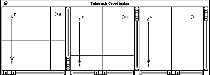
Figure 42: Talairach Image Windows with Axis and Plns options.
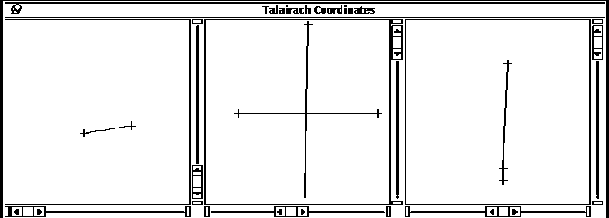
Figure 43: Talairach Image Windows with Pts option.
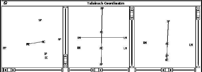
Figure 44: Talairach Image Windows with Pts, Proj
and Label options.
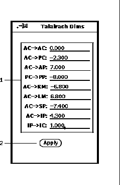
Figure 45: Talairach Dimensions popup window.
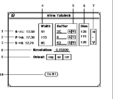
Figure 46: Xfrm Talairach popup window.


Next: Center of Mass
Up: Talairach
Previous: Talairach


![]() 5 from the volume center (41-1:6).
Then by pressing the Go Fetch! button (41-7),
those planes specified are extracted and loaded into the three orthogonal
view image displays (39-1,15,16).
5 from the volume center (41-1:6).
Then by pressing the Go Fetch! button (41-7),
those planes specified are extracted and loaded into the three orthogonal
view image displays (39-1,15,16).
![]() IC dimension field (45-1).
IC dimension field (45-1).


